Tools Required To Install Solid Roof All
All fixings supplied with roof kit. NB Fixings to house wall not supplied.
IMPORTANT: It is the installers responsibility to make sure the correct access safety equipment is used during the installation of the lcotherm Solid Roof, such as access ladders and scaffolding
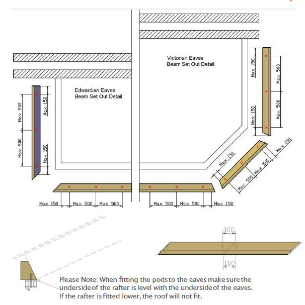
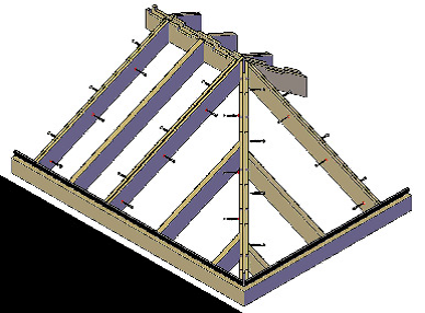
Setting the Eaves Beam
Fit the eaves to the top of the frames so the inside edge of the eaves is flush with the inside edge of the frame. Use M5 x 90professional wood screws, fixing through the frame and into the eaves beam at MAX 500mm centers & MAX 150mm in from the ends of a single eaves.
Where eaves beams are longer than 5.3 Mtr,they must be jointed at 45degrees (pre cut in the factory)and fixed to the frame either side of the joint, 100mm apart.
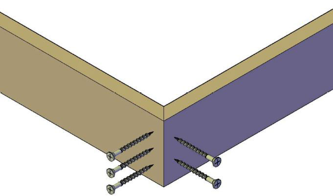
Eaves Beam Dovetail Fixing
Eaves beam to be dovetail screwed one very corner using M5 x 90mm professional wood screws supplied, 3 through one face and 2 through the opposite face 25mmfrom the external corner.Same fixing detail applies for 135°, 110° etc.
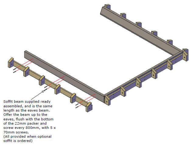
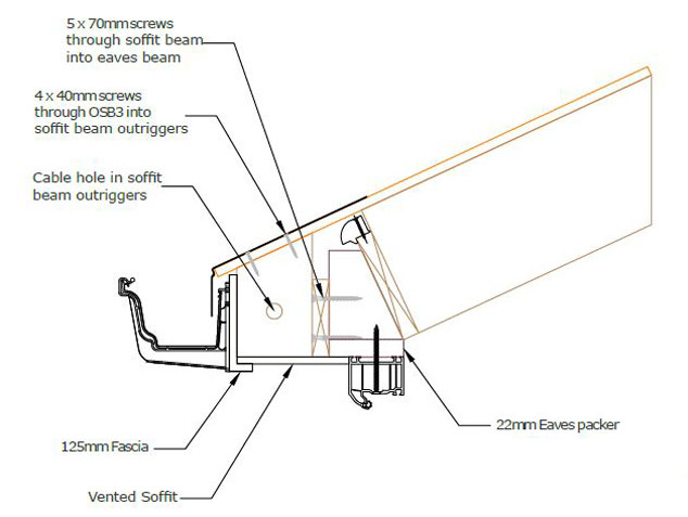
Soffit Fixing Detail
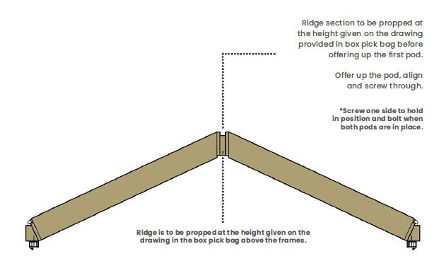
Setting The Ridge
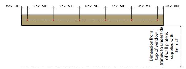
Wall Plate To Wal Fixing Detail
Concrete fixings through the wall plate 100mm infrom either side and a max of 500mm centers.
IMPORTANT:Pack wall plate where necessary.
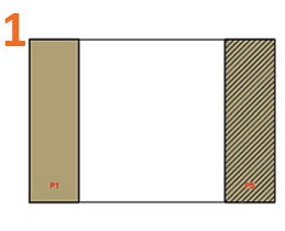
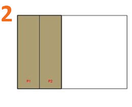
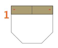
Lean-to Roof Style Pod Assembly Sequence
Once the eaves beam and wall plate have been fitted, follow this recommended pod assembly sequence for each pod before moving on to the next..
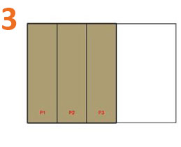
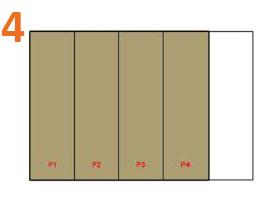
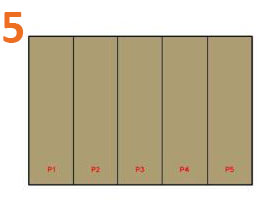
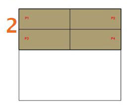
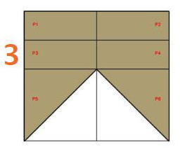
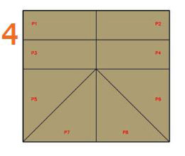
Edwardian Roof Style Pod Assembly Sequence
Once the eaves beam has been fitted follow the recommended pod assembly sequence below before moving on to the next pod.
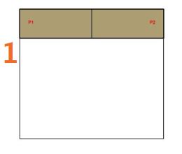
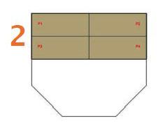
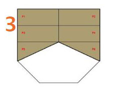
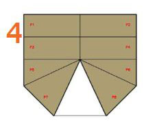
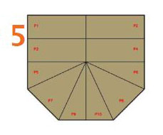
Victorian Roof Style Pod Assembly Sequence
Once the eaves beam has been fitted follow the recommended pod assembly sequence below using all the bolts and screws supplied for each pod before moving on to the next pod.
Pod Abutment Fixing Detail
| Roof Size | StaggeredScrew Centres |
| 4.9M x 5.3M | 250mm |
| 5.4M x 6.4M | 170mm |
Screws should be staggered from one side to another through all joining pod rafters, hips & valleys. Maximum dimensions of 4.8M x 6.4M for Victorian style roofs.
Wall Abutment Fixing Detail
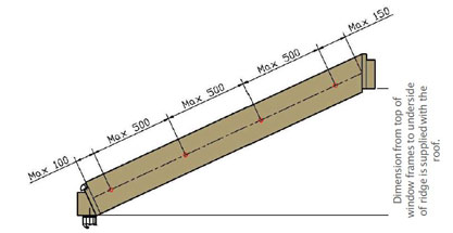
Ridge section to be propped at the height given on the drawing provided in box pick bag before offering up the firstpod. Offer up the pod at the ridge and screw through
Concrete fixings through the end rafter of the first pod, 100mm up from the bottom, 150mm from the top and a maxof 500mm centres.
IMPORTANT: only fix to the house wall after all the pods are up and fixed together..
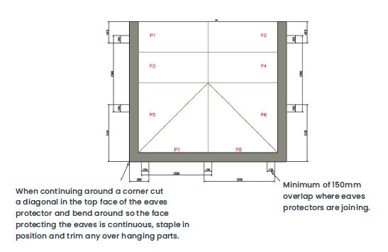
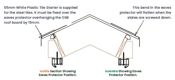
Eaves Protector Fixing Detail
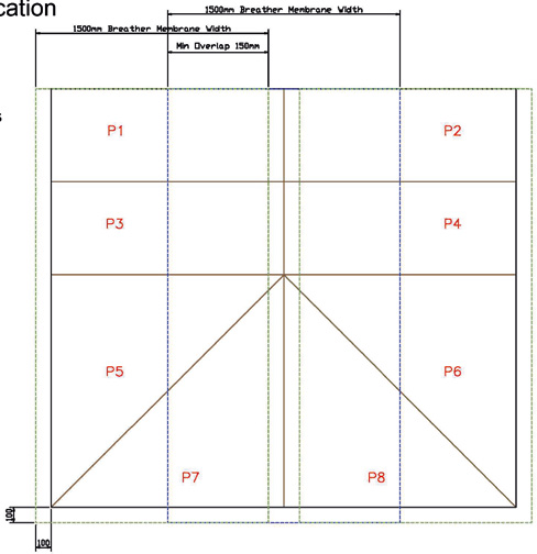
Breather Membrane Application
- Lay the first layer of Breather Membrane leaving no less than 100mm overhang around the edges and no less than 100mm up the abutment wall and staple to the roof.
- Lay the second layer in the same way,overlapping the first layer and/or ridge no less than 150mm, staple in position.
- Repeat until roof is covered, making sure that the layer above is always overlapping the layer below to allow any water/moisture to run down and over the membrane and off the roof.
- There is no need to double up the Breather Membrane on the hips as this could reduce the performance of the roof.
- If Icotile is being used then the drainage mat must be put over the breather in a similar way but does not need overlapping and can be pieced together.
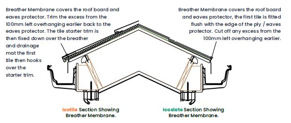
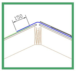
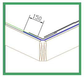
Ridges & Hips
- .Lay Breather Membrane over theridge / hip by no less than 150mm.
- Tile to be cut level with the top ofthe plywood roof board.
Valleys (with valley tray)
- .Lay Breather Membrane running in and out of the valley overlapping by no less than 150mm where necessary
- Fit the valley tray over the Breather Membrane-and overlap the valley trays by no less than150mm if needed. Valley tray to be fixed imposition on the outer most edges.
- .Ensure the tile is no less than 100mmover the valley tray.
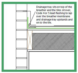
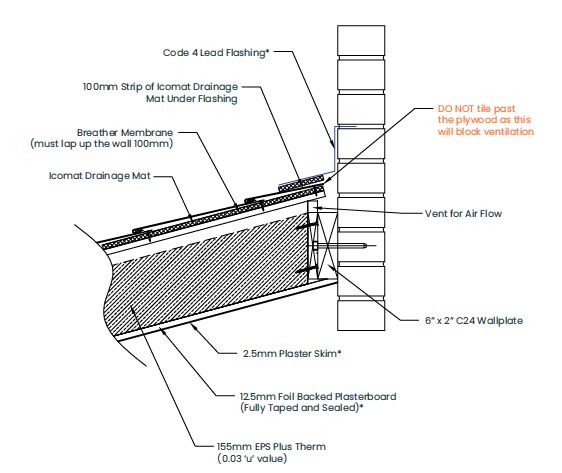
Abutments
- . Turn Breather Membrane up against abutment wall by no less than 100mm.
- Fit drainage channel over the Breather.
- Membrane trapping it between the roof board and abutment wall.
- Tile over the drainage channel being careful not to screw through it.
- Fix lead flashing Code 4 or 5, in accordance with current Codes of Practice & manufacturers recommendations
Steel Boomerang
- . Offer up the welded steel boomerang so it is centralto the pod rafter.
- . Hold in position and screw in place through the predrilled 5mm holes.
- .Drill through the 13mm pre drilled holes and throughthe rafter the steel is screwed too.
- . Fit the next pod so it is tight up to the steel and screwin position at the eaves.
- . Drill through the 13mm holes so you can bolt throughthe pods, sandwiching the steel between the pods
Insulation
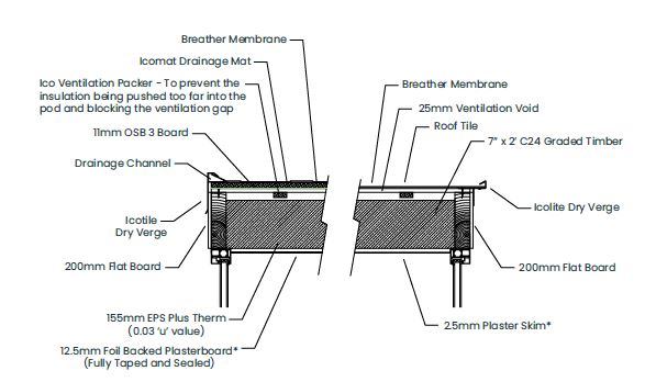
IMPORTANT: All EPS board should be tight. Any gaps to be filled with foam, being careful notto overfill and obstruct the ventilation gap.
Void must not be obstructed.
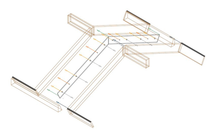
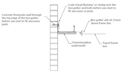
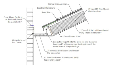
Box Gutter Detail
Lean-to Vented Ridge Finishing Detail
Solid Hips
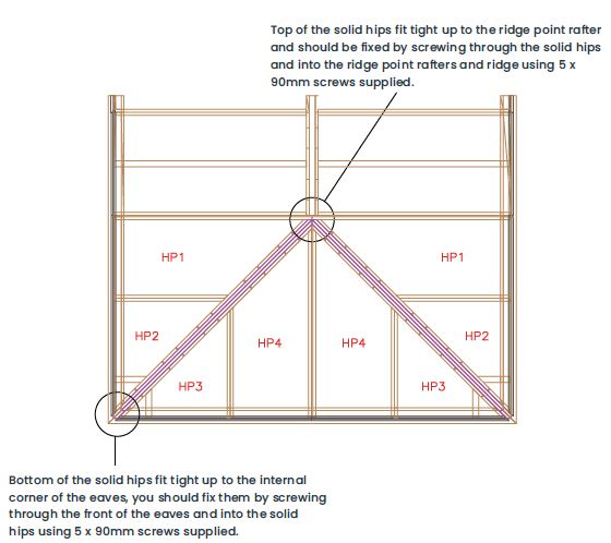
Once the rectangles are up and bolted in position you must fit HP1 on both sides before you fit the solid hip. This will give you the correct position to set the solid hips. Tack both to pod HP1 with 5 x 70mm screws supplied, screw top and bottoms indicated below. Install the remaining pods in this order - HP2, HP3 & HP4. Once all the pods are in place you can bolt through the entire hip assembly with theM10 X 130mm bolts supplied.
Icoview Pod Fitting Detail

The Ico view pod comes fully built with the glazing bars fitted (unglazed). Fit the pod so that top of the Ico View timber rafter is exactly 32mm from the top of the adjacent standard pod sbare OSB. This will ensure that the tiles run in line with the finishing top cap when complete.
Ico view Ridge Support Bar
Position the Icoview ridge support bar under the Ico tile / Ico slate ridge cap, in line with the edge.Clean the glass where the bar will be bonded to it, remove the cover tape and fix to the glass.Remove the top strip to affix to the ridge.
Note: the support bar is supplied oversized. Cut to fit between the aluminum top caps.
Glazing
Fit the glass so that the end of the double glazed unit (with the widest blacked out area)is at the bottom. Wet the gasket and slide the glass unit into place, temporarily fit thereafter glass stops.
gasket pressure bar in place over the channel and glass, with the V guide locating into the rafter bar V slot (see diagram).
Screw the metal spreader plates where the holes are in the pressure bar, using a low torque setting on your driver to avoid over tightening and distort the gasket on the glass.
Knock the powder coated top caps down and remove the rafter glass stops so you can begin tiling.
Tiling
Start from the IcoView pod top caps outwards. The tiles should be set approximately 3mm away from your top cap to allow water to trickle into the drain channel. The tiles should overhang at the eaves to be inline with the end of the rafter bar.
Once the area around the front of the Icoview pod is tiled re-fit the rafter glass stop which caps the end of the tile as well as the glass.
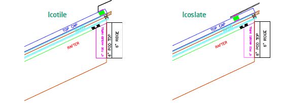
Ridge Caps
Ridge caps are fitted in exactly the same way as a standard Icotherm roof, with the addition of 2 strips of comprised at the top of the glass unit, above the blacked- out glass.
This weatherproofs the gap between the glass and the underside of the tile or tile batton.
Note: Dual Icoview pods come fully built with an engineered timber to support the central glazing bar and is fitted in exactly the same way.